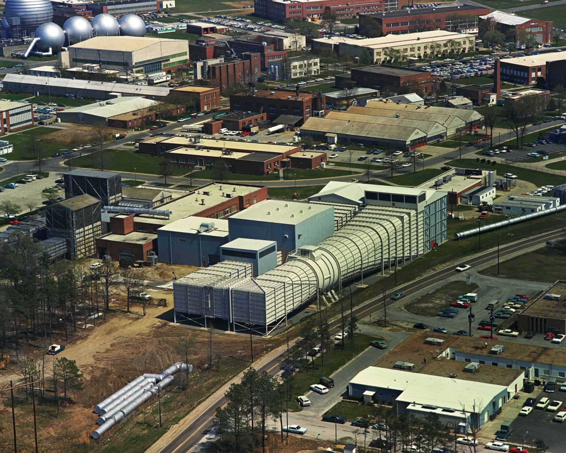
Closed circuit wind tunnel testing
Design and sizing of a closed circuit wind tunnel testing
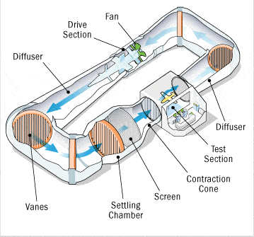
The main components of a wind tunnel testing.
The benefits of a closed circuit wind tunnel.
For the same air flow rate, the closed circuit wind tunnel can recover part of the kinetic energy and the pressure drops are only the duct losses.
In addition to the higher cost, closed loop tunnels have the disadvantage that the flow heats up.
The Reynolds number therefore lowers when instead the experiments must be kept at constant Re. We therefore need to cool the flow.
\(\begin{align} \nu(T)\propto T^{1.75}\end{align} \)The importance of temperature management in wind tunnel testing.
The tunnels can be aspirated or blown depending on the position of the propeller, whether upstream or downstream.
The energy lost through open tunnels is \( E= \frac{1}{2}mv^2 \) , the experimentation costs much more and is affected by the temperature of the experimental laboratory.
Wind tunnel classification according to test section.
Wind tunnels are also classified according to the test section.
They are divided into free vein galleries and guided vein galleries; the former are the so-called OPEN JETs in which the test section is not delimited, while the latter have a test chamber with a square, rectangular, circular, octagonal section delimited by walls, in which the corners are rounded to avoid the formation of vortices.
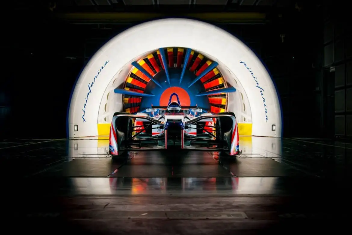
There is also a type of wind tunnel called ¾ OPEN JET, characteristics of the automotive world, in which the tunnel is delimited at the bottom, to simulate the terrain.
The Mach influence at high speed in wind tunnel testing.
For wind tunnels with a high Reynolds number, there is a tendency to intervene not only in the speed of the air flow but also from the point of view of the density of the fluid.
This is usually accomplished with cryogenic nitrogen nebulizers.
Lowering the temperature, it is as if you are considering greater Mach.
\( M=\frac{v}{v_{sound}} \) since \(\nu(T)\propto T^{1.75} \)
So lowering the temperature we can increase the Mach number and we can increase the Reynolds number.
The test chamber requirements for a wind tunnel.
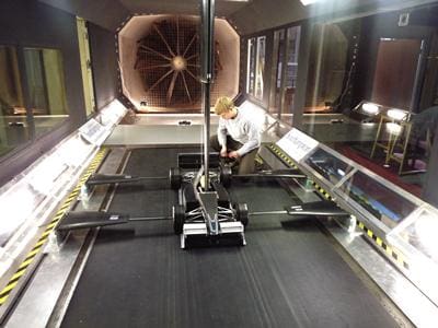
It is the place where the object to be tested is placed or where measurements are made on the flow. It is of fundamental importance to reproduce as much as possible the real conditions in which the test object is working, it is also important to have a perfectly known flow in terms of Reynolds number, turbulence level, temperature, humidity and all other variables that determine the characteristics of the flow. The test chamber is the point where the flow is at a higher speed, that is the maximum design speed of the tunnel; it is also of course the first designed component of the wind tunnel and must be large enough to accommodate the model you want to try out so as not to run into the problem of locking.
The impact of test chamber size in winf tunnel testing.
This phenomenon is in practice the effect of the walls of the test chamber on the flow lines and on the velocity of the fluid in the vicinity of the object to be tested. In all tunnels there is the effect of locking in the theoretical line, this is because if the body finds itself operating, for example in the atmosphere, it will find itself operating in a “theoretically infinite” environment while in the wind tunnel it will always find itself operating in an environment of a few square meters of section, so, if the model is small enough compared to the size of the test chamber, you can reduce this effect or in any case correct the data obtained through mathematical models, specially calibrated for the particular geometry of the chamber. test in question, implemented directly in the processors that process the data coming from the sensors in the tunnel.
Which are the main factors to correctly size a wind tunnel chamber?
To size the test chamber I have to start from the dimensions of the model and from the Reynolds that I have to create.
From the dimensions of the models that I have to analyze, considering an adequate distance from the walls to avoid forcing in the fluid I get the diameter of the test section that I have to create, and since \(\frac{L_{TS}}{D_{TS}}\approx 2 \) then I can easily obtain its length.
Estimating the bouyancy resistance in wind tunnel testing.
Important to know that the area of the test section is not constant along its length but tends to increase; this is because the viscosity gives rise to an evolutionary boundary layer (in which the thickness gradually increases) given by the v = 0 imposed by the walls on the current.
The current is as if it sees the cross section that is gradually reduced and, in the case of a subsonic tunnel, the speed increases for the conservation of the flow rate while the static pressure is reduced. Decreasing pressure leads to the emergence of a resistance force.
To calculate it, I consider an average section and multiply it by the pressure in order to know the spurious force.
\(\begin{align} \frac{\Delta p}{\Delta x}A_{media}\Delta x= F_{drag}\end{align} \)where
\(\begin{align} A_{media}=\frac{A_{ent}+A_{ex}}{2}\end{align} \)This corresponds to the resistance force (called buoyancy resistance) due to the pressure gradient.
So in the wind tunnel design phase I have to consider this slight increase in section following an angle α of about 1/2 °.
Energy dissipation in closed circuit wind tunnels.
The speed v(x) is linked to the pressure drops according to the law \( \Delta p_0\propto v^2 \) , therefore it is necessary that the speed decreases to avoid large pressure drops (where \( P_0 \) means the value of the total pressure).
For this reason, a divergent component is installed at the end of the test section to slow down the flow.
Why a divergent section is present in a closed circuit wind tunnel?
It is the component that is located after the test chamber, imagining to follow the flow of the tunnel. It has several tasks: the first is to decrease the speed by increasing the section, the second function of the enlargement of the section is purely functional to the rejoining of the conduit to the convergent in closed-loop tunnels. The slowdown of the fluid after the test chamber is fundamental because by positioning the motor, and therefore the fan or propeller in a low speed point, it is possible to install a less powerful and therefore less expensive and smaller motor. There is a positive and therefore unfavorable pressure gradient in the divergent, since the pressure at the end of the divergent is greater than the pressure value at the beginning. This leads to a thickening of the boundary layer and therefore the possibility arises of the very harmful phenomenon of separation of the boundary layer, this can be avoided with appropriate sucking devices of the boundary layer or blowing or with very small divergence angles (maximum 2 ° or 3rd). Another solution is that of rapid divergents in which nets or intermediate bulkheads are used, capable of causing the boundary layer to re-attach on the divergent wall itself.
The total pressure balance in a closed circuit wind tunnel.
For each component it is possible to determine the following balance in order to determine the pressure drops:
\(\begin{align} P_{0_{en}}=P_{0_{ex}}+\Delta P_0\end{align} \)Where \(P_{0_{en}}\) is the total pressure at the entrance of the section considered, is the total pressure at the exit of the section considered while the other term is the loss recorded in the section considered.
Sizing the divergent section in wind tunnels: first estimation.
Returning to the description of the divergent section, the angle γ of the smaller walls is, the less the losses are; however, we must take into consideration that a small angle involves a very long section length, therefore a compromise is sought between the length of the divergent and the angle of inclination of the walls.
For circular sections the angle is usually between 3 and 5 °, for sections with flat diffusers γ <6 °.
Usually the ratio between the exit area and the entrance area is 4, therefore by setting the desired angle, the required divergent length is easily obtained.
The efficiency of a divergent oscillates between 70 and 80%.
The corners in a subsonic wind tunnel.
They are used to make the flow change direction; they are made up of a duct with an angle that is suitably rounded and various wing profiles arranged in rows which have the task of facilitating the flow to bend. The curves are affected by the phenomenon of separation of the boundary layer due to the fact that they have a high curvature, and to the fact that sometimes the outlet duct has a larger section than the inlet and therefore there is an adverse pressure gradient.
The design of corners in closed circuit wind tunnels.
However, thanks to the fact that arrays of profiles are used, this annoying phenomenon can be avoided. The curves by their nature tend to introduce axial vorticity which, however, can be minimized with the use of special devices and conformations of the curves themselves.
So, after the divergent section, we can find ourselves in front of a section with a constant section or immediately an angle, which allows the rotation of the flow by 90 °, which if it has constant inlet and outlet sections has an efficiency of 80/90%.
To facilitate the curvature of the flow, the corner has deflector / deflector fins, which in the cheaper tunnels are essentially made of folded sheets, in the others by real wing profiles.
The use of wing profiles allows the insertion of pipes for the passage of coolant to lower the temperature of the current through forced convection.
Pressure loss on corners in wind tunnel testing.
This strategy makes it possible not to have additional cooling pipes along the tunnel which cause interference to the fluid, increasing the pressure drops.
Since I have high speeds in the first part, after the first corner we lost more than 50% of the total tunnel losses.
The other corners are connected by sections with a constant or divergent section which have the same characteristics as the divergent described above.
At the exit of the fourth corner, the flow occurs with minimum speed, vibration effects and the entire accumulated boundary layer of the other sections.
For the other components do not miss the next lesson!


