Understanding wind tunnel design
Closed circuit wind tunnel: settling chamber, convergent and propeller
This is our second lesson about wind tunnel design and sizing. If you missed part one, you can get it here.
Closed circuit wind tunnel design: the settling chamber.
In this section the air is manipulated because I have to break down the turbulence, straighten the flow (align it with the axis of the tunnel) so as to present a homogeneous and uniform flow to the test chamber.
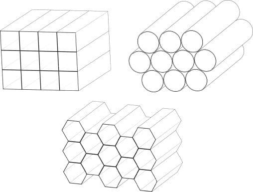
The settling chamber is composed of a honeycomb (of circular or hexagonal sections) that allow you to straighten the current both in the horizontal and in the vertical plane.
Another effect of honeycomb is that of partially breaking the turbulence of the flow according to the order of magnitude of the diameter of the sections.
Why are honeycombs important in wind tunnel?
The flow straightener of the honeycomb type is composed of a series of tubes of small diameter (generally between 5 and 7 mm) and about fifteen centimeters long. These tubes are arranged coaxially to the duct in which they are located (generally in the area of the tunnel where the speeds are as low as possible to minimize pressure drops) and are glued to each other to form structures, generally hexagonal (similar to honeycombs, hence the name), which cover the entire area of the section where they are placed.
Let’s design honeycomb for wind tunnel testing.
By way of example, it is mentioned that, in a gallery having a section where the 3.6 x 0.9 meter honeycomb is present, something like 78,000 tubes of 7 mm in diameter are arranged. The job of honeycomb is to eliminate the flow velocity components normal to the walls and to direct the flow only and as much as possible in the direction of the duct axis. Generally, honeycomb or honeycomb are placed just before the beginning of the convergent and therefore just before the test chamber.
\(\begin{align} \frac{u_{ex}’}{u_{en}’}=\frac{1}{1+k}^{\frac{n}{2}} \end{align}\)
Since the size of the vortices still remains considerable, I have to definitively knock them down with the use of one or more nets in which the flow undergoes a drastic crushing and the turbulence scale evidently decreases.
Considering the Dryden & Schubauer relationship:
Where:
\( u_{ex}’ \): fluctuations on leaving the grid
\( u_{en}’ \): grid input fluctuations
\( k \): grid performance defined by the manufacturer
\( n \): number of grids
Wind tunnel honeycombs: flow straightener.
The nets have the task of breaking large-scale swirling structures and converting them into smaller and more uniform swirling structures, thus making the velocity profile more uniform. The networks, however, have, as already mentioned, the defect of deviating the main direction of the flow, it is therefore necessary to position them around elements (the honeycomb) capable of “straightening” the flow. They are components that tend to get dirty and therefore, like honeycomb, need frequent maintenance. You can find more information about wind tunnel honeycomb in Wiki.
The flow must accelerate: the convergent section in wind tunnel testing.
Last stretch before the test chamber is the convergent which has the main task of accelerating the current.
The convergent is used to reduce the section and therefore increase the speed of the fluid while simultaneously reducing the level of turbulence and the thickness of the boundary layers on the walls. It is affected by a negative pressure gradient, and therefore favorable, (since there is more pressure at the beginning of the convergent and less at the end) there is therefore no problem of the separation of the boundary layer, this allows a fairly rapid section shrinkage. The contraction ratio is generally in the order of 6, very rarely is greater.
We are faced with a convective acceleration that does not vary over time but that depends solely on the geometry of the section.
Another effect of the convergent is to produce the reduction of longitudinal fluctuations since acceleration is as if it were stretching the flow.
Along the tunnel, small vents are often considered to adapt the pressure of the flow.
Energy balance of a wind tunnel laboratory.
Once you have calculated all the losses in the tunnel, the last step is to determine the size and power of the propeller which allows you to recover the losses and accelerate the flow for analysis in the test section.
To compensate for the pressure or pressure losses (in layman’s terms) that the fluid undergoes throughout the wind tunnel, it is necessary to introduce a certain amount of energy into the fluid every second. It is therefore necessary to equip the wind tunnel with a fan controlled by a motor. The motor (typically an electric motor that has the advantage of providing an almost constant thrust without vibrations of an reciprocating motor) can be coaxial to the fan or it can be external.
The wind tunnel propeller.
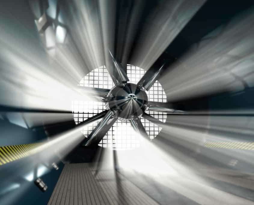
The case of the external motor is the best because it is more shielded and therefore produces less disturbance to the fluid (in acoustic terms) by heating it even less. The fan or fans are composed of one or a series of coaxial or side by side propellers; in supersonic tunnels the propellers are real axial or centrifugal compressors; they have the main task of transferring the kinetic energy supplied by the motor to the fluid in the form of pressure energy. It should be noted that, contrary to popular belief, the fan or compressor provides a pressure jump and NOT a speed jump. The transfer of course is neither adiabatic nor isentropic and this means that a part of kinetic energy is lost in heat.
Propeller and fans for the wind tunnel design.
The fan is placed downstream of the test chamber in an area with a high section to reduce the power needed to be supplied. It must also be placed as far as possible from the entrance of the test chamber according to the path that the fluid must make, so the ideal would be to place it just behind the model. However, this solution is unfavorable because at the end of the test chamber the speed is maximum for two main reasons: 1) in the test chamber the goal is always to have the maximum speed; 2) at the end of the test chamber the boundary layer is thicker than the central area of the test chamber, and this causes a decrease in the effective section seen by the fluid. This means that the speed is even higher than at the beginning of the test chamber; the fan is therefore placed at the end of the divergent, where the local speed is lower.
To prevent the flow after the propeller from rotating, I also insert stator blades to straighten the current.
The position of the propeller is dictated by performance and cost.
The best compromise between inlet flow speed and flow turbulence is to position the propeller after the second corner.
Boundary layer treatment for automotive wind tunnel testing.
For automotive wind tunnels:
From the convergent, once the flow is straightened and the turbulence is reduced, the boundary layer in the lower wall is born again before it enters the test section.
To avoid this phenomenon, two stratagems are used:
– Aspiration of the boundary layer upstream of the model through a series of small holes.
– Moving Belt: treadmill that allows you to change the boundary condition of zero speed on the wall which has the effect of not forming a boundary layer.


