Practical tyre models: slip angle and slip ratio
Slip ratio and slip angle influence on vehicle performance
Longitudinal force: slip ratio and slip angle.
We continue the previous chapter talking about longitudinal forces, slip ratio and slip angle.
As we told at the beginning of these articles about tires, no acceleration can take place without a force acting between the tread and the ground in accordance with the Newton’s second law and the same (with a reverse direction) goes for the braking.
With longitudinal forces created by tractive and braking torques is fundamental to introduce the slip ratio.
Slip ratio definition.
The slip ratio (SR) is defines as:
\(\begin{align} SR= \frac{s}{\omega_0}=\frac{\omega-\omega_0}{\omega_0}=\frac{\omega}{\omega_0}-1\end{align} \)Where \( s=\omega-\omega_0 \) is the longitudinal slip velocity, in other words the difference between the angular velocity of the wheel minus the angular velocity of the free-rolling wheel.
In free-rolling SR = 0, \(\frac{\omega}{\omega_0}=1\) (the speed of the wheel is equal to the speed of the free rolling wheel).
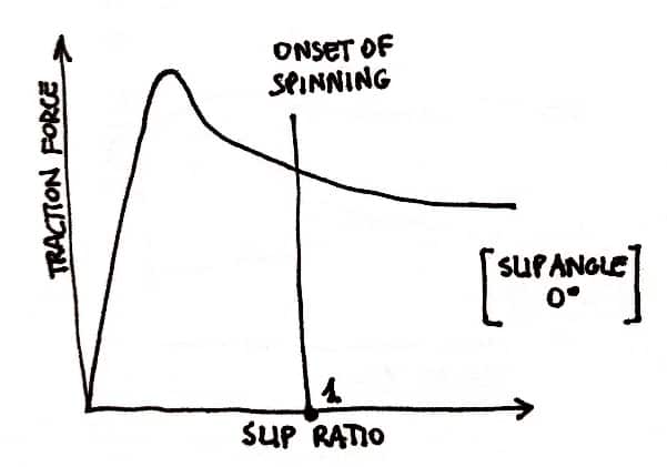
In spinning SR = 1, \(\frac{\omega}{\omega_0}=2\) (the speed of the wheel is twice the speed of the free rolling wheel – defined arbitrary).
Note that we considered the slip angle α=0. If this is not true, we have to introduce the term with the velocities, important if traction and braking forces are carried on under cornering conditions.
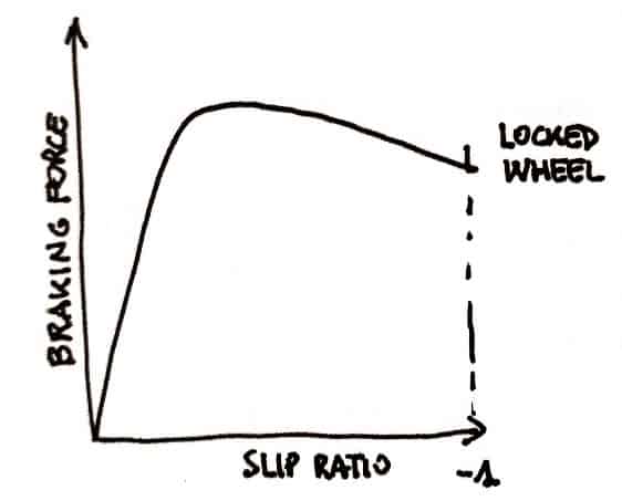
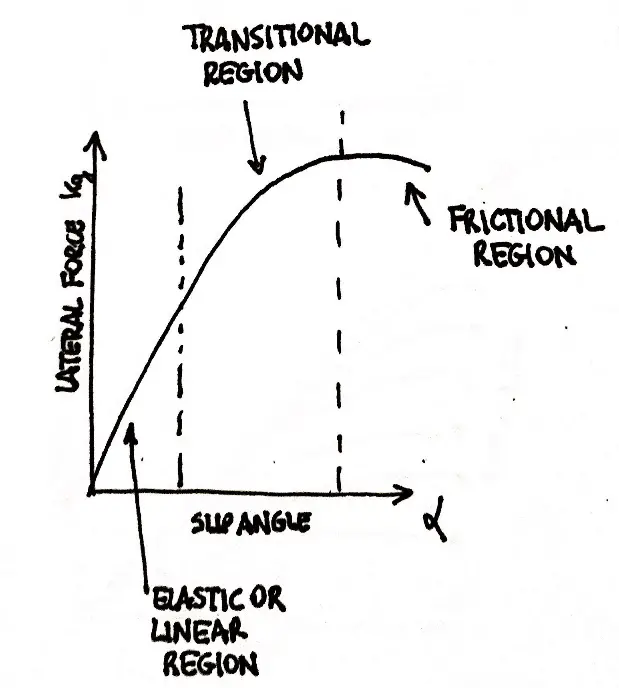
The tractive or braking forces depends on the slip ratio as shown in the following pictures.
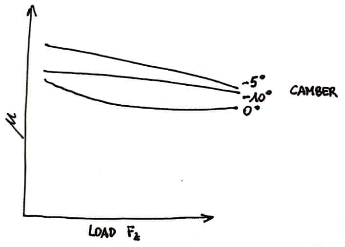
The camber angle affects slip angle and slip ratio.
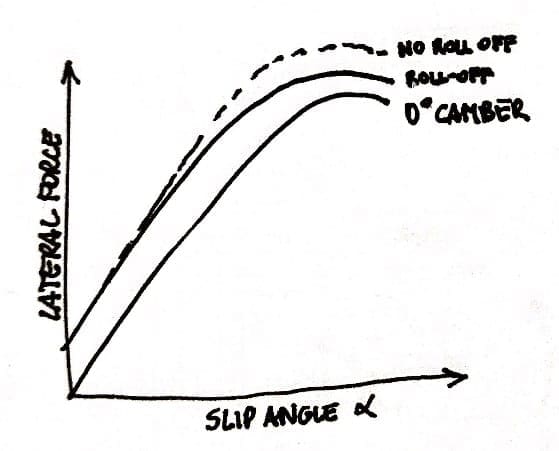
As we saw in the chapter referred to the camber, a cambered rolling tire produces a lateral force in the direction of the tilt (camber thrust).
Obviously, camber raises a lateral distortion in the footprint of the tire and this affects the pneumatic trail and so the aligning torque.
Due to the decrease of the distance between the fore and the aft of the print the aligning torque in a cambered wheel is little bit less than an uncambered wheel and therefore we have a little destabilization of the aligning torque that increase the slip angle; this may require an increase in mechanical trail to produce the desire centering effect.
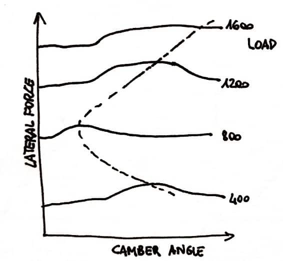
Using the collected data, we can approximate the desirable camber for the outside front wheel for a range of vertical loads to maximize Fy/Fz.
The pressure effect on slip ratio and slip angle.
Tire pressure is one of the easiest and most common changed made in setting un a race car. The range of permissible pressures is frequently set by the tire manufacturer.
With the pressure we can manage the stiffness of the tires; if the tire pressure is raised the carcass will get stiffer and so the cornering stiffness will increase.
Lowering the contact pressure between the rubber tread and the road raises the effective friction coefficient, and increases the size of the footprint and lowers the contact pressure in the print.
However, too low an air pressure creates localized high-pressure areas at the sides of the print due to the sidewall stiffness. The general idea is to set the air pressure such that the center tread and the edges of the tread carry a proportional share of the load.
As the pressure is decreased, the print becomes longer and the center of lateral force moves rearward. When a tire loses air, steering effort for a given lateral acceleration turn is increased because of the decrease in cornering stiffness and the increase in aligning torque.
Tire drag will be decreased by an increase in pressure.
What is the best tire pressure for slip angle and slip ratio?
The best tire pressure is a compromise between many factors, the best performance is achieved with higher pressures, the best grip with lower pressures and the optimal pressure can be found only by experimentation.
The pressure differs from the camber (for example) because it is not a constant value during the race or generally during the rolling of the tire. That’s the reason why we usually speak about hot pressure and cold pressure, referred for the pressure fully operational and for the pressure inflated in the tire before the session.
So, mechanics and engineer define the optimal cold pressure that’s the pressure that in fully operation conditions reach the optimal hot pressure given by the tire manufacturer.
Example of a FW drive car.
Talking about front wheel drive touring car, here below an example of tire pressures (we speak in “bar” values but in F1 and other championships values are given in “psi”):
| Cold Pressure (bar) | Hot Pressure (bar) | |
| F slick | 1.40 | 2.10 |
| R slick | 1.70 | 2.10 |
| F rain | 1.80 | 2.20 |
| R rain | 2.00 | 2.20 |
Pressures can be different between front and rear tyres: the firsts are responsible of traction and steering so they heat faster (and more) than the rear ones.
Usually, rain tyres are made of a different structure so their optimal pressures may differ from the slick ones. Note that track conditions, grip, air temperatures and brand of the tires can change a lot the values in the table.
The temperature effect on slip angle and slip ratio.
Tire temperature affects both the force-producing capability of the tire and also the life of the tire. A change in temperature will change the modulus of elasticity of the rubber and there’s an optimum value for maximum grip. Temperature changes with track condition and pressure of the tire.
Just to give you some numbers, in touring race car a classical example of good heated tire (also with a proper camber angle) is given by 105°C degrees in the inner area of the tread, 95°C in the middle and 85°C in the external one.
