What is rolling resistance in tyres
Rolling resistance: origin and design parameters
The origin of rolling resistance.
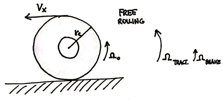
The upright wheel rolling freely, that is without applying a driving torque, over a flat level surface long a straight line at zero side slip, may be defined as the starting situation with all components of slip equal to zero. A relatively small pulling force is needed to overcome the tyre rolling resistance and a side force and self-aligning torque may occur as a result of the not completely symmetric structure of the tyre.
When the wheel motion deviates from this by definition zero slip condition, wheel slip occurs that is accompanied by a build-up of additional tyre deformation and possibly partial sliding in the contact patch.
\(\begin{align*} r_e=\frac{V_x}{\Omega_0}\end{align*} \)
Longitudinal slip: \(\begin{align} \kappa=-\frac{V_x-r_e\Omega}{V_x}=-\frac{\Omega_0-\Omega}{\Omega_0}\end{align} \)
where \( \Omega \) denotes the angular velocity in traction or braking; the lateral slip is defined as \( \tan\alpha=-\frac{V_y}{V_x} \)
The parameters affecting the tyre rolling resistance.
Newton’s first law says that “a body remains in its state of quiet or uniform rectilinear motion until a force intervenes to modify this state”.
The motion of any body is the result of the interaction of forces acting on it. As mentioned, several times in these chapters, the movement of our vehicles also derives from the combination of a certain number of forces, which can be grouped conceptually into traction units, if they allow advancement, and resistant, if they oppose the motion of the vehicle or side.
The driving forces naturally include the traction forces exchanged between the tires and the ground, but also include all those external actions that cause the vehicle to move in the direction of motion (the pull due to the use of towing or recovery devices, the gravitational component on downhill sections, etc.).
Resistant forces are all those actions that oppose the movement of the vehicle and therefore include: the rolling resistance of the tires, the aerodynamic resistance, the resistance due to the slope, the frictions in the transmission organs, the resistance caused by the sinking of the wheels in the ground, etc. Each of them acts with greater or lesser continuity and entity according to the conditions of use, but among them there are two that are always present during the movement of a vehicle: the aerodynamic resistance and the rolling resistance of which the former strongly depends from the forward speed of the vehicle.
Rolling resitance and performance.
Without running into aerodynamics, treated here, rolling resistance is the result of all the energy losses that occur during the rolling of a tire. Referring to the tire only and not to the surface of the ground, these losses are to be found basically in:
- Hysteresis due to the viscoelastic nature of the rubber that makes up the tire;
- Friction generated in the slippage between tire and ground;
- Aerodynamic heating elements caused by air, both internal and external to the tire.
Of the three phenomena above, the one that provides the preponderant contribution is certainly the first. The hysteresis losses, in fact, give a contribution between 80 and 95% to the rolling resistance, while only a part between 20 and 5% is attributable to other phenomena.
Elastic hysteresis is the phenomenon that occurs when the energy used to deform a body is not fully returned.
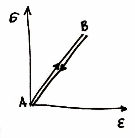
If you deform a body made of perfectly elastic material, the tension (σ) – deformation (ε) curve will have the trend of fig. 1: the curve going from the initial condition A to the deformed condition B will be completely superimposable on the return curve.
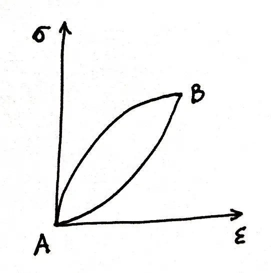
Instead, if I go to deform a body made of viscoelastic material (for example a rubber plug), the tension (σ) – deformation (ε) graph will have the trend of fig. 2: the forward and return curves will not follow the same path and therefore the body will not return the same amount of energy that I used to deform it.
During the rolling of a tire, the losses due to elastic hysteresis derive from the continuous deformation cycles to which the tire structure is subjected and occur 70% at the tread, 15% at the sidewall and the remaining 15% on the heel.
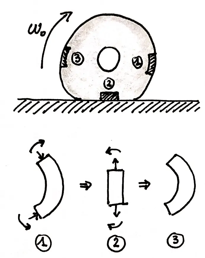
Fig. 3 shows a very schematic illustration of what happens to a piece of tread during its rotation motion.
Due to energy losses, an asymmetry is created in the distribution of the tire contact pressure which translates into a torque that opposes rolling.
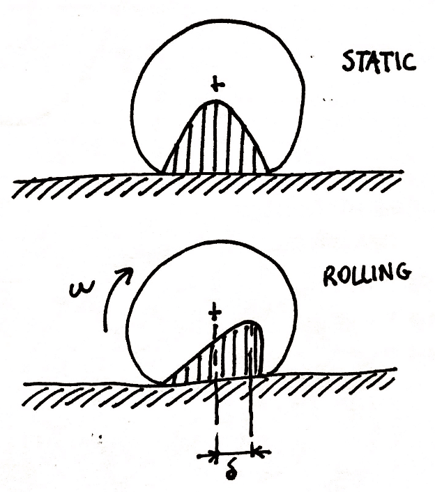
Difference in the distribution of contact pressures between the static and rolling conditions of the tire. The offset between the vertical load on the tire and the reaction force of the ground gives rise to a torque that opposes the movement of the tire.
Rolling coefficient definition.
With a few simple mathematical steps, we arrive at the conclusion that the rolling resistance Fr is directly proportional to the vertical load Q according to the term f, called the rolling coefficient. To overcome this resistance, I can apply a driving torque (driving wheel) or push the wheel with a horizontal force (driven free wheel).
\(\begin{align} C_r=Q\cdot\delta\end{align} \)
where \( C_r \) is the resistant moment.
\(\begin{align} F_rR_c=Q\cdot\delta\end{align} \)
\(\begin{align} F_r=Q\cdot\frac{\delta}{R_c}\end{align} \)
\(\begin{align} F_r=Q\cdot f\end{align} \)
The parameters that influence the rolling coefficient are varied: the inflation pressure, the temperature, the rotation speed of the wheel, the type of tire, the braking or pulling torque applied, the state of wear of the tread, the characteristics of the ground.
For example, addiction to the speed changes according to the type of tire. Compared to cross-ply tires, radials, in addition to having lower rolling coefficients, also have less increases than the latter as speed increases.
An increase in the inflation pressure reduces the rolling coefficient on firm ground as it results in less deformability and therefore less elastic hysteresis. On the other hand, on yielding soils, higher inflation pressures lead to higher contact pressures and therefore greater sinkings with consequent greater resistance to advancement.
The increase in tire temperature reduces the rolling coefficient in two ways: on the one hand, it warms the air inside the carcass by increasing the inflation pressure; on the other hand, it reduces the hysteresis of the rubber.
Rolling coefficients: typical values and examples.
As you can imagine, just as the irregularity of the ground surface affects the rolling coefficient, the type of tread also has a certain weight on its value.
These are just some of the numerous and complex interactions that can, depending on the operating conditions, influence the rolling coefficient in a more or less accentuated way.
The rolling coefficient normally assumes values that can be ten or even a hundred times lower than those of the adhesion coefficient.
Table below shows the typical values of the rolling coefficient for some types of surface.
| Surface | Rolling coefficient |
| Tarmac | 0,006-0,013 |
| Pavè | 0,015 |
| Gravel | 0,02-0,025 |
| Dirt road | 0,05 |
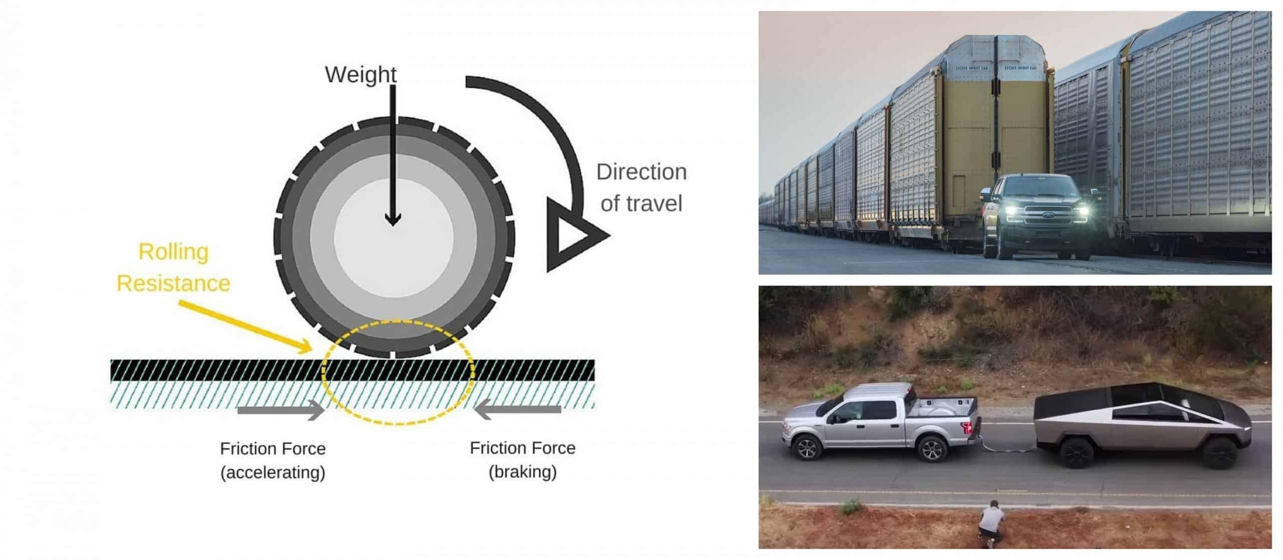
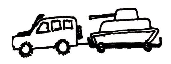
Let’s take a simple example. Let’s consider a tank on a trolley, so that it has wheels and not the tracks in contact with the ground. To move such a vehicle on asphalt, it is enough to multiply its weight of the complex by the relative rolling coefficient.
\(\begin{align} F_r=Q\cdot f= 75000\cdot 9.8\cdot 0.008=5880 N\end{align} \)
Taking a rolling coefficient value of 0.008 (average value among those typical for trucks), we find that about 760 kg are enough to move 75000 kg.
In addition, assuming a plausible value of 0.8 for the adhesion coefficient [\latex]\mu [/latex], we conclude that the 75-tonne articulated lorry can potentially be moved by a vehicle with a total vertical load of only 750 kg available on the drive wheels.+
\(\begin{align} m= \frac{5800}{9.8\cdot 0.8}=750 kg\end{align} \)
Considering for example an off-road vehicle, generally weighting about 2 tons, it is easy to see how having 4 wheels and assuming that the weight is uniformly distributed, each wheel has a vertical load of about 500kg (therefore at least 1000kg if two-wheel drive) and is successful to tow the heavy tank.

